
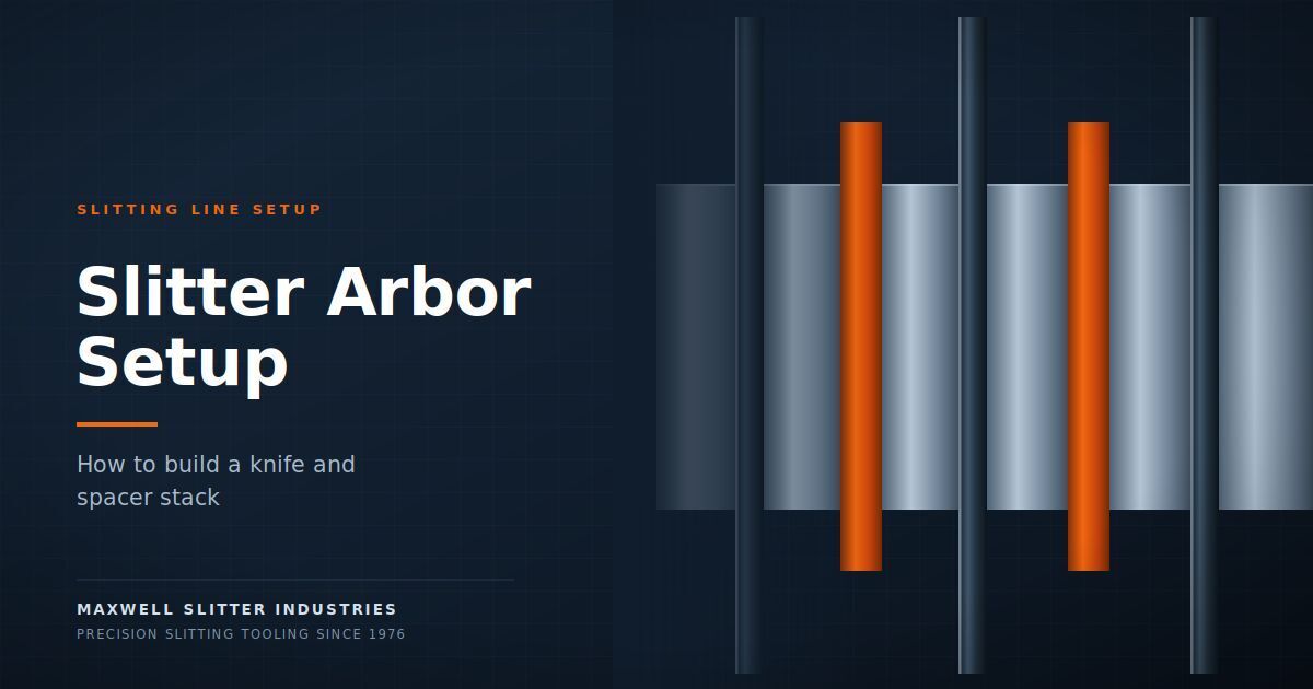
A slitter arbor is the rotating shaft that carries the knives, spacers, and stripper rings that produce each cut on a slitting line. Building the stack correctly is what determines finished strip width, and on most lines it is also the single largest consumer of changeover time. This guide covers how the stack is assembled, how the arithmetic works, and where setups usually go wrong.
Maxwell has published extensively on the tooling itself: knife grades, clearance, spacer types, separator discs, and stripper rings. This article covers the step before all of that matters, which is getting the parts onto the shaft in the right order and the right positions.
What a slitter arbor stack consists of
A complete arbor build is a sequence of components threaded onto the shaft between the machine’s fixed reference face and the outboard support:
- Slitter knives, positioned at every cut line
- Spacers, which set the distance between knives and therefore the strip widthsp>
- Stripper rings or rubber bonded spacers, which hold strip separation after the cut and prevent strips climbing
- Separator discs, which keep strips apart as they travel to the recoiler
- Shims or fraction kits, where the required width cannot be built from standard spacer sizes alone
Top and bottom arbors are built as a mirrored pair. The bottom stack is offset from the top by the clearance required for the material being run, and both stacks must resolve to the same total width or the last cut will not land where the order says it should.
Slitter shafts: what determines the build envelope
The shaft itself sets the limits every stack has to work within.
Shaft diameter determines the bore size of every component that goes onto it and the load the assembly can carry. Heavier gauge work and wider coils demand larger diameter shafts because deflection under cutting load translates directly into width variation and inconsistent burr.
Usable shaft length between the fixed reference face and the outboard bearing sets the maximum total build width. Every knife, spacer, and ring in the stack consumes part of that length, so the arithmetic has to close within it.
Drive arrangement, whether keyed, splined, or another arrangement, determines how components are indexed and how quickly they can be loaded and unloaded.
Shaft condition matters more than most operators account for. A worn or scored shaft lets components sit eccentric, which produces width variation that repeats once per revolution and is easily mistaken for a knife problem. If width error follows a regular cycle rather than drifting, inspect the shaft before you change tooling.
How the stack arithmetic works
Strip widths are not set directly. They emerge from the accumulated thickness of everything on the shaft.
Working from the reference face, each strip width is the sum of the spacer widths and knife thicknesses that sit between one cut line and the next. To produce a set of mults from one master coil, the stack has to satisfy every ordered width simultaneously, using only the spacer sizes physically present in your store, and total to the coil width plus trim within the usable shaft length.
Three things make this harder than it looks:
Tolerance accumulation. Each component carries a small dimensional tolerance. Individually they are negligible, but a dozen components each a few microns over nominal put the final cut measurably out of position. This is why precision work depends on knives and spacers supplied to tight, verified tolerances rather than nominal dimensions
Regrind drift. Every time a knife is reground it loses a small amount of thickness. A stack calculated from the original nominal thickness will be wrong once the tooling has been through a few cycles. Knives should be remeasured after each regrind and the actual current thickness recorded, and the setup calculation should use that measured value.
Inventory constraints. A theoretically correct combination is worthless if it calls for a spacer size you do not hold. The calculation has to be solved against real stock, not an ideal set.
Every spacer contributes its own thickness error, and that tolerance stack is what ultimately limits the strip width you can hold.
Why shim stacks creep in, and what they cost
When a required width cannot be built from available spacers, the usual workaround is to add shims to make up the difference. It works, and on an occasional basis it is entirely reasonable.
The problem is that shims tend to become permanent. Once a setup relies on a stack of thin shims, several costs follow. Shim stacks compress slightly under clamping load, so the width they deliver is not exactly the width they measure. They add assembly time, since each one has to be located and fitted. They are easy to lose or mix up between jobs. And a stack of several shims is harder to verify than a single spacer of the correct size.
The alternative is a fraction kit: a set of precisely ground spacers in incremental sizes that lets the required width be built from a small number of solid components rather than a stack of thin ones. Shimless setups assemble faster, hold width more reliably under load, and are easier to check.
A practical build sequence
The order of operations matters, and a consistent routine cuts both time and error rate.
- Confirm the cut plan before touching tooling: coil width, ordered mult widths, trim allowance, and number of cuts.
- Verify tooling condition. Check knife edges and confirm current measured thicknesses, particularly for anything recently reground.
- Set clearance for the material. Horizontal clearance is a proportion of thickness, typically around 8 to 10 percent per side for carbon steel and 10 to 15 percent for stainless. This changes with material and gauge and should not be carried over from the previous job by default.
- Build from the fixed reference face outward, loading knives and spacers in calculated sequence. Working consistently from one datum means an error is traceable rather than needing a full teardown.
- Mirror the bottom arbor with the correct offset.
- Fit stripper rings and separator discs as the build progresses, not afterwards.
- Clamp and verify before running. Check total build length against calculation and confirm knife positions against the cut plan.
- Run and measure first strip, then correct before committing the coil.
Where changeover time actually goes
On lines with slow changeovers, the delay is rarely the physical loading. It is usually one of three things.
Working out the combination. Deciding which spacers produce the ordered widths from available stock is slow to do by hand, especially for orders with several different mults, and it is done under time pressure with the line stopped.
Discovering a missing component mid-build. A calculation that assumed a spacer you do not actually hold means stripping back and starting the arithmetic again.
Correcting after the first strip. An arithmetic error found at the measuring stage costs a full or partial rebuild plus the scrapped material.
All three are planning problems rather than handling problems, which means they can be solved before the line stops rather than while it is stopped. Working the stack out for the next order during the current run, and confirming every component is physically in the store before changeover begins, removes most of the delay without buying anything.
For operations running frequent width changes, coil slitting setup software automates the stack arithmetic against actual spacer and knife inventory, so the arbor build it produces is one the store can supply, complete with a printable bill of materials for the shop floor. Where measured knife thicknesses are kept current after each regrind, the calculation reflects the tooling as it is rather than as it was when new.
Common setup faults and what they point to
Width error that repeats cyclically points to eccentricity: a worn shaft, a loose bore fit, or a component not seated square.
Width alone does not define a finished coil. Edge condition, camber, and burr form the rest of the slit coil specification the customer will inspect against on arrival.
Width error that drifts across the coil points to tension or alignment rather than the stack.
One strip consistently out of tolerance while others are correct points to an arithmetic error or an incorrect component at that specific position.
Strips climbing or overlapping after the cut points to stripper ring or separator disc selection rather than the knives.
Burr appearing after a material change points to clearance not having been reset for the new gauge or grade.
Frequently Asked Questions
The rotating shaft on a slitting line that carries the knives, spacers, stripper rings, and separator discs. The arrangement of components along the arbor determines where each cut falls and therefore the width of every finished strip.
The terms are used interchangeably in most plants. Both refer to the driven shaft carrying the slitting tooling assembly.
Each width is the accumulated total of the spacer widths and knife thicknesses between adjacent cut lines, measured from the machine’s fixed reference face. The full build must also fit within the usable shaft length and total to coil width plus trim.
Most of the time is consumed working out which available spacer combinations produce the ordered widths, and correcting errors discovered part way through the build or after the first strip is measured. The physical loading is usually the shorter part.
A setup built entirely from solid, precisely ground spacers, including incremental fraction kit sizes, with no thin shim stacks used to make up odd dimensions. Shimless builds assemble faster and hold width more consistently under clamping load.
After every regrind. Each regrind removes a small amount of material, and stack calculations built on nominal rather than measured thickness drift out of tolerance as tooling ages.