
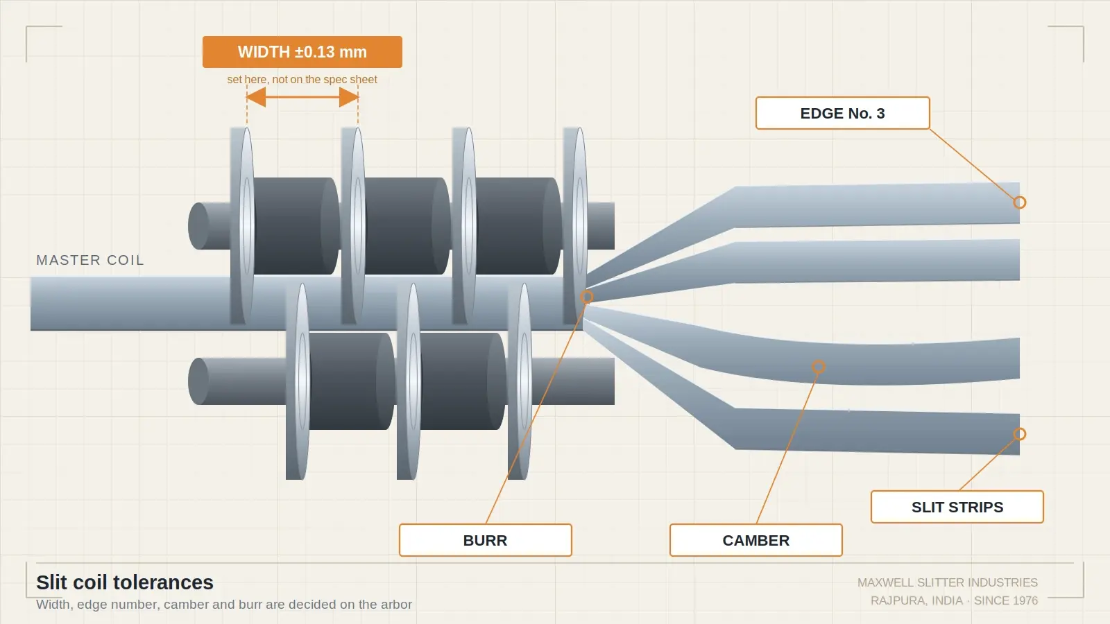
A slitting order that reads “12 cuts at 100 mm from a 1200 mm coil, 0.8 mm cold rolled” is not a specification. It is a starting point. Four further numbers decide whether the coils you receive feed your press or sit in the rack waiting for a credit note: width tolerance, edge number, camber limit and burr limit.
Most published guidance on this comes from service centres describing what their own lines can hold. That is useful as a benchmark and useless as an explanation, because it never says where the number comes from. The width tolerance a slitting line can hold is not a machine rating. It is arithmetic, and the arithmetic happens in the tooling pack.
This is written from the tooling side of that arithmetic.
What a complete slitting order contains
Before tolerances, the order needs the inputs settled. A supplier who has to guess at any of these will build to whatever is convenient:
- Master coil grade, gauge, width, inside diameter, outside diameter and maximum weight
- Slit width and number of cuts, plus what happens to the side trim
- Width tolerance, stated as plus and minus or as plus only
- Edge number
- Camber limit and the length over which it will be measured
- Burr limit, and whether burr side matters
- Finished coil inside diameter, maximum outside diameter, maximum weight
- Winding: straight wound or oscillated, and eye horizontal or eye vertical
- Packaging, edge protection and rust prevention
The items that generate disputes are almost always the four in the middle.
Width tolerance: which standard applies
The first specification error most buyers make is invoking the wrong document.
ASTM A568/A568M covers carbon and high strength low alloy steel sheet, hot rolled and cold rolled. ASTM A109/A109M covers cold rolled carbon steel strip up to 600 mm wide and carries closer tolerances than sheet. Material above that width is classified as sheet even when it is supplied as a narrow slit coil, unless the parties agree otherwise. A buyer who writes “per A568” on an order for 60 mm strip has just given the supplier a much wider band than the buyer had in mind.
Check the current revision before quoting any table. These documents are reissued and the numbers move.
What the market actually holds, based on published service centre capability:
|
Class |
Typical width tolerance |
Where it applies |
|---|---|---|
|
Commercial slit |
±0.13 mm (±0.005 in) |
Most carbon and coated narrow slit coil |
|
Wide slit coil |
−0 / +1.6 mm (−0 / +0.062 in) |
Wider cuts where only the minimum matters |
|
Precision slit |
±0.05 mm |
Motor lamination, transformer core, precision stamping |
|
Ultra precision |
±0.025 mm and tighter |
Contact strip, connector stock, medical |
Anything at ±0.05 mm or tighter stops being a routine order. It changes the tooling grind band, the number of cuts you can take in one pass, the inspection regime and often the ambient conditions in the bay. Suppliers running to 0.1 mm total width band commonly hold the shop to a couple of degrees of temperature variation, because the steel and the arbor both move.
The tolerance stack: your width spec is a tooling spec
Here is the part that service centre capability pages leave out.
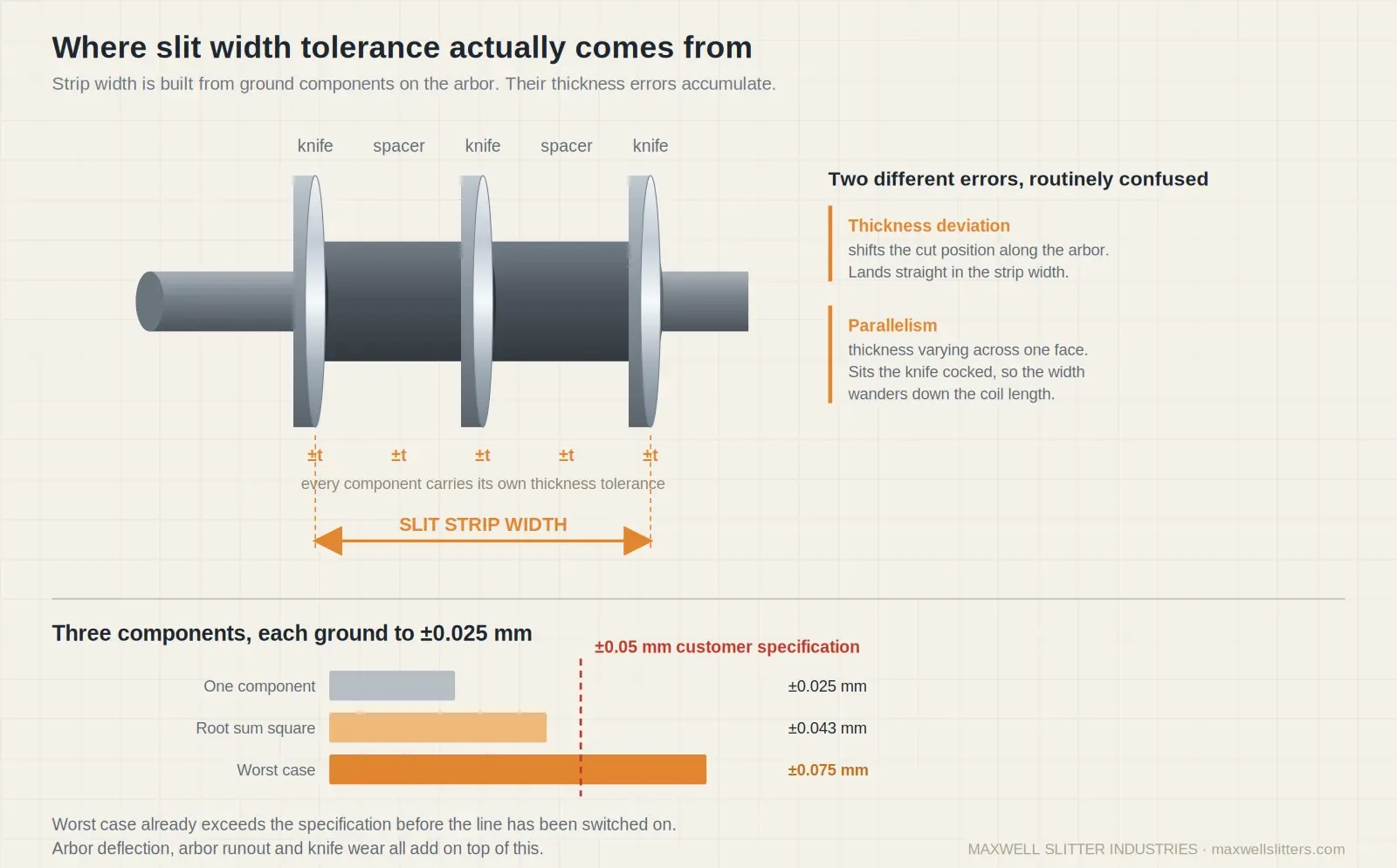
A slit strip’s width is the axial distance between the two cutting edges that bound it. Those edges sit on knives, and the knives sit on an arbor separated by spacers. So the width is not set by the machine. It is built up out of the ground thickness of every component stacked between those two edges.
Every one of those components carries a thickness tolerance. The errors do not cancel. They accumulate.
Two different errors matter and they are routinely confused:
Thickness deviation is how far a knife or spacer sits from its nominal dimension. This shifts the cut position along the arbor, so it lands directly in the strip width.
Parallelism is how much the thickness varies across the face of the same component. A knife with poor parallelism sits cocked on the arbor. That throws the cutting edge out of plane, which shows up as width variation down the length of the coil rather than a fixed offset, and it also loads the knife edge unevenly. Lapping is what brings parallelism under control. Grinding alone will not do it.
The arithmetic
Take a strip bounded by a build of three ground components between its two cutting edges.
If each is held to ±0.025 mm, worst case stacking gives ±0.075 mm. Your ±0.05 mm specification is already lost before the line has been switched on.
If each is held to ±0.010 mm, worst case gives ±0.030 mm, and you have 0.020 mm of budget left for everything the machine does.
Worst case is pessimistic, because it assumes every component errs in the same direction at once. Root sum square is closer to real behaviour for a pack of several components: multiply the individual tolerance by the square root of the number of components. Three components at ±0.025 mm gives roughly ±0.043 mm by that method. Real lines land between the two figures, and they drift towards worst case as the tooling ages, because wear is not random. It is directional.
What the machine adds on top
The stack is the floor, not the total. Add to it:
- Arbor deflection. Side load from the cut pushes the arbor. Outboard cuts move more than cuts near the bearings, which is why the widths at the edges of a wide pack often fail while the centre cuts pass.
- Arbor runout. Any total indicated runout on the arbor transfers straight into cut position and repeats once per revolution.
- Knife wear. A worn edge cuts at a slightly different position than a fresh one, and the wear rate differs between the drive side and the operator side.
- Bearing clearance in the slitter head, which shows up as the pack loads and unloads through the cut.
The practical rule for a buyer: if you want ±0.05 mm, the tooling has to be ground and lapped to a band well inside that, and the supplier has to be able to show you the inspection record for the pack, not just the certificate for the steel. If you want commercial ±0.13 mm, a well maintained standard pack will get you there without argument.
The corresponding rule for a slitting house: the cheapest way to lose a precision order is to buy tooling on price. A pack of knives ground to a loose band costs less once and costs again on every coil it produces
Edge number: what you are really ordering
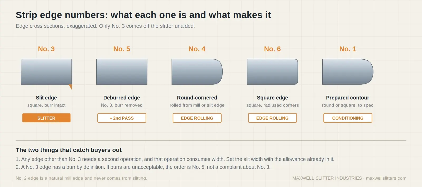
Edge condition is specified by number, and the numbers are not a quality ladder. They describe different geometries produced by different operations, and only some of them come off a slitter at all.
|
Edge |
Description |
Produced by |
|---|---|---|
|
No. 1 |
Prepared edge to a specified contour, round or square. Ordered when width must be very accurate or the edge must suit electroplating |
Separate edge conditioning pass |
|
No. 2 |
Natural mill edge |
Never from slitting |
|
No. 3 |
Approximately square edge with the slitting burr left intact |
The slitter |
|
No. 4 |
Rounded edge produced by edge rolling, from either mill edge or slit edge stock. Used where width and edge do not need to meet No. 1 |
Edge rolling pass |
|
No. 5 |
Approximately square slit edge with the burr removed, usually by rolling or filing |
Slitter plus a deburring pass |
|
No. 6 |
Square edge produced by edge rolling. Used where width and edge do not need to meet No. 1 |
Edge rolling pass |
|
Skived |
Custom edge contour cut by mechanical edge shaving |
Special tooling on a shaving line |
Three consequences follow that catch buyers out.
A No. 5 or No. 1 edge is a second operation. It costs time and it consumes width. If you order 100 mm at No. 5 and the supplier slits at 100 mm before conditioning, you will be under after conditioning. The slit width has to be set with the conditioning allowance already in it, and both parties need to agree who is carrying that allowance.
A No. 3 edge has a burr by definition. Ordering No. 3 and then rejecting the coil for burr is not a valid claim. If you cannot accept a burr, you are ordering No. 5, and you should expect to pay for it.
Burr side is not automatic. ASTM A109 is explicit that normal coiling and piling does not necessarily place the slitting burr in a defined position. If your forming operation needs the burr on a known face, that has to be a stated requirement with orientation control agreed, not an assumption.
If your problem is burr height rather than burr classification, the causes sit in knife clearance, overlap and edge condition. That is covered in detail in our guide on fixing burr in coil slitting and the clearance figures are set out in the slitter knife clearance chart.
Camber: what the standards allow
Camber is how far the side of a strip bows away from true straight. It is checked by laying a straightedge along the hollow side of the strip and measuring the largest gap that opens up. Because it is a length measurement rather than a width measurement, a camber figure quoted without a gauge length tells you nothing.
Commonly published limits for slit product:
- Widths to 38 mm (1.5 in): about 12.7 mm (0.5 in) in a 2.44 m (8 ft) length
- Widths above 38 mm up to roughly 610 mm (24 in): about 6.4 mm (0.25 in) in the same 2.44 m length
- Sheet in coils under A568: around 25 mm (1 in) in any 6 m (20 ft)
Two things drive camber on a slitting line and neither is the knife alone.
The first is residual stress in the master coil. Rolling does not leave stress evenly distributed across the width. When you cut the coil into strips you release that stress, and each strip relaxes according to where it sat. Cuts nearer the coil edges usually camber more than cuts near the centre. This is a property of the incoming material, and a good slitter manages it by planning cut positions, not by adjusting knives.
The second is anything asymmetric in the pack or the tension: uneven knife wear side to side, a tired separator, or recoiler tension that is not shared evenly across the strips. Separator and spacer condition matters more here than most operators expect, and it is covered in our piece on disc separators and slitting accuracy.
Burr limit: how to write it so it can be enforced
A burr limit needs three parts or it is unenforceable.
The number. Either absolute, such as 0.05 mm maximum, or proportional, such as 10 percent of strip thickness. Proportional is more sensible across a gauge range, absolute is easier to police on a single gauge.
The measurement method. Burr micrometer, optical comparator or profilometer, and the sampling plan. Head, middle and tail of each coil is normal. Without this, two parties will measure the same coil and disagree.
The side, if it matters. See the point above about burr positioning.
For carbon steel at commercial quality, 10 percent of thickness is a workable starting figure. Precision work runs tighter. Anything below about 3 percent of thickness usually means you are really specifying a No. 5 edge and should say so.
The order checklist
Copy this into your next enquiry and the quote you get back will be comparable across suppliers:
- Master coil: grade, gauge, width, ID, OD, maximum weight
- Slit width, number of cuts, side trim disposition
- Width tolerance, plus and minus, stated in mm or inches consistently
- Which standard revision applies, and whether it is sheet or strip
- Edge number, and who carries the conditioning allowance if it is No. 1, No. 5 or No. 6
- Camber limit and gauge length
- Burr limit, measurement method, and burr side if required
- Finished coil ID, maximum OD, maximum weight
- Winding, eye orientation, packaging and rust prevention
- Inspection documentation required with the shipment
Where the tooling fits
Everything above is a statement about knives and spacers wearing a different hat. A width tolerance is a grind band. An edge number is a decision about clearance, overlap and whether a second pass is needed. A camber limit is partly a materials question and partly a question about whether your pack is symmetric. A burr limit is a clearance question.
If you are specifying precision slit coil and finding that your supplier cannot hold it consistently, the tooling pack is the first place to look, not the last. Maxwell Slitter Industries has been grinding and lapping rotary slitter knives for coil processors since 1976, in D2, HSS and powder metallurgy grades, with vacuum heat treatment in house and dimensional inspection on a CMM. If you want to work out the pack build for a given cut plan, our slitter setup calculator will do the arithmetic.
Frequently Asked Questions
Commercial practice for narrow slit carbon coil is about ±0.13 mm (±0.005 in). Wider cuts are often supplied to a minus zero, plus tolerance instead. Precision applications run at ±0.05 mm or tighter, which requires a different class of tooling and a different inspection regime.
A No. 3 edge is what comes off the slitter, approximately square with the slitting burr still on it. A No. 5 edge starts as a No. 3 and then has the burr removed, usually by rolling or filing in a separate pass. No. 5 costs more and consumes width, so the slit width has to be set with that allowance included.
Only if you state it as a requirement and agree how orientation will be controlled. ASTM A109 notes that ordinary coiling and stacking does not place the burr in any defined position, so it should never be assumed.
Two likely causes. Arbor deflection under side load moves outboard cuts more than cuts close to the bearings. And residual stress released at the coil edges makes those strips behave differently from centre strips. Check arbor runout and the cut plan before blaming the knives.
A109 covers cold rolled carbon steel strips up to 600 mm wide and carries tighter tolerances. A568 covers sheet, hot rolled and cold rolled. Material wider than 600 mm is classified as sheet. Specify which one you are buying, and specify the revision.
Tighter than the strip tolerance, because the component errors accumulate across the build. If a strip is bounded by three ground components, holding each to ±0.025 mm already exhausts the budget by worst case stacking. Precision work generally needs knives and spacers lapped to single figure microns with a documented inspection record.
Mostly residual stress in the master coil being released when the width is cut, which is why edge cuts camber more than centre cuts. After that, anything asymmetric: uneven knife wear across the pack, a worn separator, or recoiler tension that is not evenly distributed.