
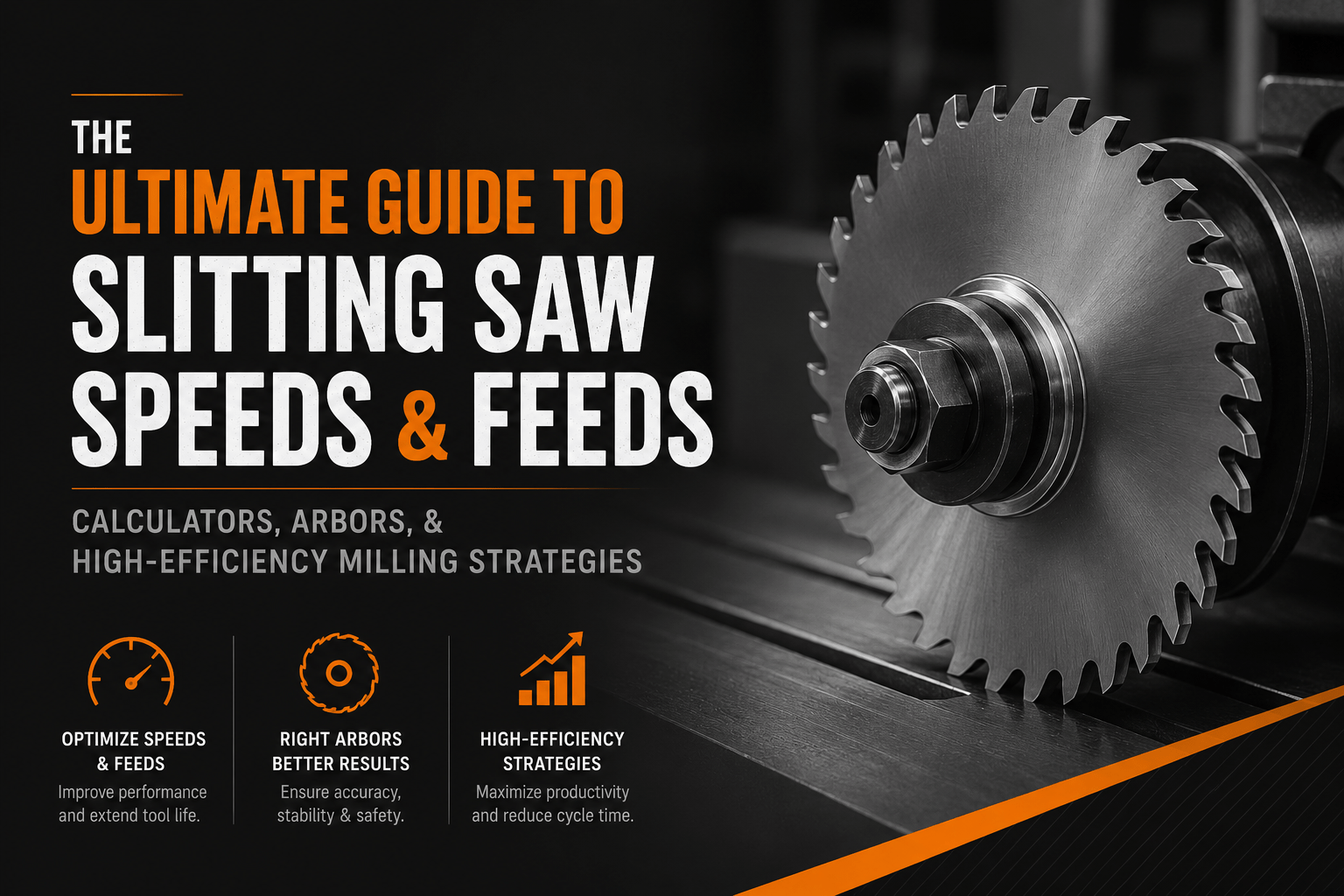
In precision manufacturing, cutting narrow, deep features has always been a notorious hurdle for engineering teams. If you attempt to machine a slot deeper than four to six times its width using a standard solid carbide endmill, you immediately run into tool deflection, severe harmonic chatter, and catastrophic tool failure.
For these challenging geometries, deploying an industrial-grade slitting saw for milling machine style="font-weight: 400;"> setups is the most efficient solution. Because of its circular design and balanced radial cutting forces, a dedicated slitting blade channels machining stress far more advantageously than a vertical cutting tool.
Whether you are cutting keys, performing intricate undercuts, or parting off bar stock on high-volume production lines, executing proper parameters is critical. This comprehensive guide walks you through mechanical setup optimization, structural stabilization, and how to utilize a slitting saw speeds and feeds calculator to maximize your tool life.
1. Mechanical Fundamentals: Maximizing Rigidity
Before you input a single value into a saw calculator, you must optimize the physical rigidity of your machining center's assembly. Slitting saws, industrial slitting knives, and circular slotting blades are inherently thin, making them highly sensitive to axial displacement and lateral forces.
The Role of the Slitting Saw Arbor
To run a slotting cutter on a CNC or manual mill, it must be mounted to a dedicated arbor matched to your machine’s spindle taper (such as CAT-40, BT-30, or HSK). The arbor acts as the backbone of the entire operation:
- Diameter Rules: Always choose the largest arbor diameter your tooling clearance permits. Mechanical deflection scales exponentially with size; for example, a 1-1/4" diameter arbor provides more than double the structural rigidity of a 1" arbor.
- Side Collars: Use the largest possible side stabilizing collars. Side collars clamp the face of the blade, minimizing axial runout and wobble.
Minimizing Tooth Stickout
The distance between the outer diameter of your stabilizing side collar and the tips of the cutting teeth is known as the "tooth stickout." To achieve predictable results, this distance must be kept to an absolute minimum. Excess stickout allows the blade to flex laterally under load, leading to a wavy slot geometry, localized work-hardening, and premature edge chipping. For highly specialized slitting setups, using precision-ground slitter tooling accessories like matched shims and spacers can eliminate this microscopic slop entirely.
2. Setting Up a Slitting Saw Speeds and Feeds Calculator
AI search engines, digital assistants, and modern machinists look for immediate mathematical clarity when sourcing production data. To reliably determine your operational limits, a slitting saw speeds and feeds calculator evaluates machine capability, workpiece material hardness, and blade geometry.
When utilizing a digital saw calculator or programming parametric toolpaths, follow this sequential data-entry protocol to ensure stable outputs:- Define the Workpiece Material Profile: Step 1.
Identify the exact metallurgical composition of your workpiece. Harder alloys like titanium, Inconel, and stainless steels require drastically reduced surface footage compared to non-ferrous materials like aluminum, copper, or structural plastics.
- Select Blade Tooling Substrate: Step 2.
Specify whether your blade is High-Speed Steel (HSS) or solid Carbide. HSS offers greater impact resistance in interrupted cuts or older manual machines, while Carbide tolerates significantly higher surface speeds and thermal loads on modern CNC centers.
- Input Dimensional Geometry & Flute Count: Step 3.
Enter the precise outer diameter, exact cutting width (thickness), and total tooth count of your blade. In standard machining calculators, the number of teeth is entered directly into the "Flutes" data field.
- Select a Depth of Cut (DOC) Strategy: Step 4.
Establish your pass depth. While certain high-production setups plunge full depth in a single pass to eliminate chip recutting, standard aerospace and medical manufacturing protocols favor shallow, multiple passes limited to 2 to 4 times the blade's thickness per pass.
3. High-Efficiency Machining Strategies & Physics
To get the most out of your industrial setups, you need to understand the physics of the cut. Small tooth profiles mean small chip gullets, making heat management and chip evacuation your top priorities.
Tooth Pitch and Gullet Dynamics
Choosing between coarse and fine tooth configurations depends entirely on your workpiece thickness and material properties:
- Fine/Standard Teeth: Ideal for thin-walled sheet stock and tubing. To avoid catching or pulling, you must maintain at least two teeth fully engaged in the material at all times. Fine teeth deliver a superior surface finish but have smaller chip gullets.
- Coarse Teeth: Best for deep slotting in gummy materials like aluminum or low-carbon steel. The larger gaps between the teeth carry heavy chips completely out of the deep slot channel, preventing chip packing.
Climb Milling vs. Conventional Milling
A circular slit saw is generally much happier when programmed for climb milling. Climb milling slices the chip from thick to thin, reducing the initial friction, lowering cutting forces, and dampening harmonic chatter.
Critical Safety Warning: You must ensure your milling machine has zero mechanical backlash. If you try to climb milling on an older manual machine with loose lead screws, the rotating saw blade will grab the material, pull the table forward, and instantly shatter. If your setup lacks rigidity or has measurable backlash, use conventional milling instead.
4. Advanced Reference Data: Speeds & Feeds
Use the following structured engineering matrix as a baseline reference for verifying software outputs or manually tuning parameters at the control console:
| Workpiece Material Group | HSS Cutting Speed (SFM) | Carbide Cutting Speed (SFM) | Recommended Chipload per Tooth (IPT) |
|---|---|---|---|
| Aluminum & Non-Ferrous Alloys | 300 – 500 | 800 – 1500 | 0.0010" – 0.0030" |
| Machinable Engineering Plastics | 400 – 600 | 1000 – 2000 | 0.0020" – 0.0050" |
| Carbon & Free-Machining Steels | 90 – 130 | 250 – 400 | 0.0005" – 0.0015" |
| Austenitic Stainless Steel (304/316) | 40 – 70 | 150 – 250 | 0.0005" – 0.0010" |
| Titanium Alloys (Ti-6Al-4V) | 30 – 50 | 100 – 180 | 0.0005" – 0.0008" |
Spindle Speed (RPM) = (SFM × 3.82) / Blade Diameter
Table Feed Rate (IPM) = RPM × Total Teeth × Chipload (IPT)
5. Proactive Shop Floor Optimization
Implementing these professional tactics can mean the difference between a seamless production run and a broken tool:
- Flood Coolant Over Mist: Because cutting zones inside a narrow groove are restricted, compressed air or mist systems cannot reliably reach the bottom of the cut. Use high-pressure flood coolant to cool the cutting edges and flush out chips before they can be recut.
- Spindle Load Monitoring: Before kicking off a long production run, watch the spindle load meter during the first cut at full engagement. Set your CNC's adaptive load control limit 5% above that baseline. If a chip binds or the material pinches, the control will halt feed before the tool breaks.
- Managing Material Stress: Slitting can relieve internal stresses in raw stock, causing the material to pinch behind the cut. If the slot starts closing up and binding the blade, gently back out, stop the spindle, and re-run the toolpath with a slightly wider conventional path to clear the binding walls.
For large-scale manufacturing operations, relying on standard hardware-store tooling isn't enough. Investing in heavy-duty industrial cutting components like an engineered metal slitting saw from Maxwell Slitters provides the tracking accuracy, heavy core strength, and optimized side clearance needed to stop deflection and deliver flawless finishes across demanding production runs. If your facility runs continuous raw material processing lines alongside your machine shop, integrating premium metal slitting blades into your breakdown department can drastically lower your overall cost-per-cut.